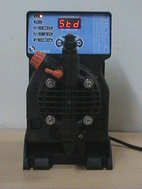
Electronic dosing pumps incorporate the same drive, control and liquid design features as the series pumps. Their housing is made of corrosion resistant, impact resistant, glass fibre reinforced NORYL Plastic. Thus, they are insensitive to aggressive dosing media or vapours, meet the splash proof and dust proof requirement of protection class IP 65.
The electronic control of these pumps an advanced development derived from the experience gained in long term manufacture of electronic dosing pumps has been realised in high quality hybrid technology, which guarantees the proverbial reliability of electronic dosing pumps, under continuous operating conditions. As a standard feature, all electronic dosing pumps allow easy change over from internal to external mode with the help of a knob. In external mode, pump can be operated through potential free contact upto a maximum of 6000 contacts per hour.
Electronic pumps have complete independent adjustability of the required quantity delivered per stroke and stroke frequency, giving rise to infinitely adjustable dosing from 0.4% to 100% while at the same time ensuring optimum performance to the variety of demands made by the water treatment process.
These pumps have the following advantages:
U.V.Tech Systems Pressure Sand Filter is specially designed to trap turbidity and suspended impurities from raw water upto 15 Micron size or more at relatively high flow rates which range from a mere 250 lph to 3,00,000 lph according to the capacity required.
The Filter media employed is clean sieved graded Quartz sand, as Quartz sand has a unique property which doesn’t allow the trapped suspended solids in the water to stick to it and thus are easily removed. For application like iron removal, chlorine scavenging etc., special media like MnO2, Activated carbon etc. is used.
U.V.Tech Systems is of standard Engineering Design confirming to ISI standards. The Material of Construction for the Pressure vessels is of three varieties namely Stainless Steel 304,316 / Mild Steel /FRP (Fibre Reinforced Plastic). MS/SS Vessels are fitted with dished ends, man-holes, supporting legs and facing pads for pipe connections.
The MS Vessel is painted internally with Epoxy and externally with Red Oxide. It is also fitted with a set of internal distribution systems and collection systems for Filteration, Rinsing and Backwashing of water. A Set of Pressure Gauges for inlet and outlet connections is also provided.
The FRP Vessels are designed and tested for High Pressure Flow and last much longer than MS vessels. They are fitted with Multiport Valves which give all the operations by A SINGLE VALVE OPERATION and thus are cost effective & easy to use. They do not require any painting or maintenance. Moreover the advantage is that they are of food grade quality and can be used even in the food industry. They are also light in weight and can be easily mounted on rooftops of residential premises.
In stainless steel vessels we maintain the highest quality by using SS 316 material for construction. These vessels are non corrosive and last longer than any kind of material of construction. Here the advantage is that there are no welded points in the whole pipeline as we give triclover fittings for connecting the entire pipeline. This gives an added advantage of dismantling the whole plant within 45 minutes without any tools. These vessels are internally and externally polished to maintain high quality standards.
We can also give completely automatic valves for labour free operations. These valves can be set according to time intervals or based on the amount of flow required from the water treatment plant. Once set according to the requirement they can perform the operation flawlessly for any number of times.
U.V.Tech Systems ACTIVATED CARBON is used for physical adsorption. Like graphite, Carbon is a reducing agent that reacts with strong oxidizing agents such as chlorine di-oxide, hypochlorous acid and ozone. As we normally add chlorine to the raw water to primarily disinfect the water, we also have to remove the chlorine as its presence in the water may produce bad odour & is considered bad for health. As activated carbon is a good adsorption agent, It removes all the free chlorine from potable water. Physical adsorption also removes bad taste and odour, volatile organic compounds (VOCs), trihalomethanes (THMs) and other halocarbons from drinking water.
U.V.Tech Systems ACTIVATED CARBON FILTER is of standard Engineering Design confirming to ISI standards. The Material of Construction for the Pressure vessels is of three varieties namely Stainless Steel 304,316 / Mild Steel /FRP (Fibre Reinforced Plastic). MS/SS Vessels are fitted with dished ends, man-holes, supporting legs and facing pads for pipe connections.
The MS Vessel is painted internally with Epoxy and externally with Red Oxide.. It is also fitted with a set of internal distribution systems and collection systems for raw filtered and backwashing water. A Set of Pressure Guages for inlet and outlet connections are also provided.
The FRP Vessels are designed and tested for High Pressure Flow and last much longer than MS vessels. They are fitted with Multiport Valves which give all the operations by A SINGLE VALVE OPERATION and thus are cost effective & easy to use. They do not require any painting or maintenance. Moreover the advantage is that they are of food grade quality and can be used even in the food industry. They are also light in weight and can be easily mounted on rooftops of residential premises
In stainless steel vessels we maintain the highest quality by using SS 316 material for construction. These vessels are non corrosive and last longer than any kind of material of construction. Here the advantage is that there are no welded points in the whole pipeline as we give triclover fittings for connecting the entire pipeline. This gives an added advantage of dismantling the whole plant within 45 minutes without any tools. These vessels are internally and externally polished to maintain high quality standards.
We can also give completely automatic valves for labour free operations. These valves can be set according to time intervals or based on the amount of flow required from the water treatment plant. Once set according to the requirement they can perform the operation flawlessly for any number of times.
Reverse Osmosis (RO) is a modern process technology to purify water for a wide range of applications, including semiconductors, fisheries, food processing, biotechnology, pharmaceuticals, power generation, seawater desalting, and municipal drinking water.
Reverse Osmosis is the cost effective water purification system it is an immediate source of pure water. The process of reverse osmosis (RO) represents the finest level of liquid filtration available today. And though the term sounds mysterious, reverse osmosis isn't really that complicated.
Ordinary water filters use a screen to separate particles from water streams. The holes that these Filters have are fairly large. This allows just about everything that is dissolved in the water to pass through as well. An RO system employs a semi-permeable membrane. The membrane is a thin, multi-layered sheet with pores so small that water molecules can pass through, but it acts as a barrier to dissolved solids like salts and other chemicals. Thus even Bacteria and viruses are trapped and not allowed to pass through.
Maximum purity is attained by reducing
Reverse Osmosis systems remove salts, micro-organisms and high molecular weight organics. The System capacity depends on three major factors.
For waters with Total Dissolved Solids of 200 ppm or more, Reverse Osmosis is less expensive than Ion Exchange. Even on comparable water it has better sediment and organic removal capabilities. Compared with Distillation, Reverse Osmosis uses only a fraction of the total energy and does not have high temperature problems, scaling and corrosion.
Compared with other conventional water treatment processes, Reverse Osmosis has proven to be the most efficient means of removing salts, chemical contaminants and heavy metals, such as lead, from drinking water.
A simple illustration to show how RO works to purify water is provided.
Reverse Osmosis is a membrane separation process in which feed water flows along the membrane surface under pressure. Purified water permeates the membrane and is collected, while the concentrated water, containing dissolved and undissolved material that does not flow through the membrane, is discharged to the drain.
With cross-flow filtration, the feed stream continuously flows across the membrane; anything that does not go through the membrane gets carried off with the cross-flow and is sent to the reject port. In this way the "Reverse Osmosis" process can continue non-stop without clogging the membrane.
Reverse osmosis can treat a wide variety of health and aesthetic contaminants that cause unpleasant taste, color, and odor problems like a salty or soda taste caused by chlorides or sulfates. RO can also be effective for treating health contaminants like arsenic, herbicides/pesticides, lead, mercury, nitrate, and radium.
U.V.Tech Systems Micron Filter Catridges are manufactured to give considerable dirt holding capacity coupled with high flow rates and low pressure drops and can provide you with an absolute micron size of upto 0.2 M. These are generally placed in a decreasing order from 5, 1, 0.45, 0.2 M. so that each takes similar load and thus they can maintain a longer life. Catridge elements cannot be backwashed but are generally treated as disposable” elements.
The Micron catridge elements consists of a perforated support core of plastic or metal into which yarn is wound at a pre-set rate providing each rating of element with its own distinctive winding pattern and performance. During the winding process the yarn is usually brushed (or napped). This has the effect of increasing the working area of the elements thus providing a higher dirt holding capacity whilst maintaining the rigid structure.
Standard PP Catridge are suitable upto 90 deg.C although a tin or stainless steel core can extend this to 125 deg C for short periods. Other fibers such as polyester and cotton, nylon and rayon can operate at higher temperatures and have differing chemical compatibility. For very high temperatures and for very strong oxidising agents baked glass fibre elements are used. Glass fibre elements are fitted with voiles as standard and other cartridges can also be fitted with voiles whenever necessary.
Micron Filters come in the following types of Housings and Cartridges:
1. Housings:
2. Cartridges:
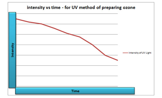
Ozone is a pungent gas naturally produced in the Earth's upper atmosphere by the action of UV sunlight on oxygen molecules. Ozone can be created for water treatment purposes by sending air through a special chamber containing a high-voltage "spark," which creates a blue plasma corona; it is also produced by sending air through a chamber of ultraviolet light
Ozone is a powerful oxidizer similar to chlorine. Many of the same benefits we get from chlorinating water (disinfection, oxidation of metals, etc.) is also realized by using ozone gas, except that with ozone, there is no chemical residual left in the water. Chlorine can combine with organic material in water to produce toxic compounds, such as "THMs"
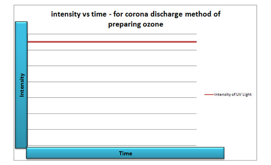
Because of its active characteristic, ozone cannot be stored. So it is generated on-site near its point of use. Ozone is generated by the exposure of air or pure oxygen to a high-energy source such as a high voltage electrical discharge (corona discharge), photochemical reaction (UV light), high or low electrical frequencies or high-energy radiation. The most widely used procedure is the corona discharge method because it produces the highest concentration of ozone for the amount of electrical energy applied and currently is considered to be the only practical method of generating ozone in large scale quantities
In the corona discharge method a dry, oxygen-containing gas (air or pure oxygen) is passed between two electrically charged plates separated by a ceramic dielectric and a narrow discharge gap while a high voltage alternating current is applied. Under these conditions a portion of the oxygen in the feed gas is converted to ozone in the following manner:
O2+e 2[O] +heart
2[O] +202= 203
Because ozone is only slightly soluble in water, at the partial pressure at which it is generated and applied, contacting ozone with water involves bringing bubbles of ozone-containing air or oxygen into intimate contact with the water.
The ozonation process may be divided into four main parts: gas preparation, electrical power supply, ozone generation and contacting. Associated with these basic components are additional subunits such as controls, instrumentation, cooling water and/or cooling air supply, Ozonized gas and water are generally brought into close proximity in a contactor, usually a venturi injector type. Mass transfer of ozone from the gaseous bubbles occurs across the gas/liquid interface into the water.
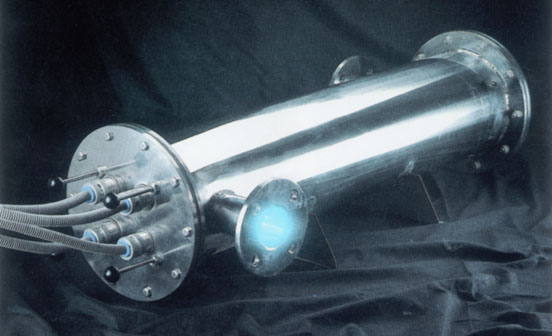
Ultra Safe Ultraviolet Water Purifiers are manufactured from stainless steel 304/316/316L/FRP. The Radiation chamber is mirror polished from the inside and outside thus reflecting max amount of radiation. Both the ends are flanged for easy operation, maintenance and servicing.
Specially designed reflectors give additional U.V. reflection to get maximum efficiency. Units are designed to get maximum retention time and turbulence of water for better results. The U.V. Lamps are housed in quartz sleeve and assembled in Stainless Steel Shells. Each quartz jacket is provided with a specially designed wiper assembly for removing any particles that get settled on the Quartz tube
The wiper assembly is specially designed for easy operation without stopping the operation of the unit. The system is completely sealed to avoid any harmful effects from U.V. radiation. All wetted rubber parts are made of Food Grade Silicon Rubber to avoid bad odour & detraction due to U.V. radiation.
The Power Panel of the system is specially designed to withstand voltage fluctuation upto 5% +. All the U.V. Cables are protected with spiral shield. The U.V. lamps are provided with indicator lamps to show the burning of U.V. lamps. An alarm system can be provided to give signal in case of any lamp failure (Optional).
They are available in capacities ranging from 100 ltrs. /hr. to 1, 00,000 ltrs. / Hr.
The Effluent Treatment Plant consisting of following major units
The wastewater generated from various sections is to be segregated into two streams. (Sullage – wastewater from kitchens, wash waters from bathrooms etc. and Sewage – the wastewater from toilets) and treated.
The sullage would be let through bar screen chamber, grit-settling tank/oil and grease trap, and Sullage collection tank. From the sullage collection tank it is regulated and pumped to the chemical precipitation tank where coagulants are dosed using automatic dosing pumps. The overflow goes to the sullage settling tank and chlorination/filter feed tank where chlorination is done. From here it is pumped to pressure sand filter and pressure carbon filter for final polishing. The sludge from the settling tank is pumped periodically to the sludge tank. The non- biodegradable bar screenings like plastics, cloth pieces, rubbers etc to be removed and disposed to the solid waste disposal system. For Chlorination and Pressure Filtration same tank and same pressure filters are used for both sullage and sewage.
The sewage would be let through the bar screen chamber to the collection tank. The non- biodegradable bar screenings like plastics, cloth pieces, rubbers etc to be removed and disposed to the solid waste disposal system.
From the Collection/Primary settling tank the wastewater is pumped at the required regulated flow to the Anaerobic Tank
The anaerobic tank contains the high surface area fixed fill media, which is stationary and anaerobic reduction of organic matter takes place here. This ensures development of high anaerobic microbial bio-growth and the anaerobic microbial biomass reduces the initial organic load in sewage (From B.O.D 350 mg/l to 210 mg/l).
The overflow from the anaerobic tank overflows to the Diffused Aeration tank where the aerobic bacterial growth is allowed to grow in suspension and the process employed is Activated sludge process. The aerobic bacteria attain a high growth rate utilizing the oxygen supplied by the diffused aeration system and reduces the organic matter. Diffused aeration system comprises of diffusers, which are installed at the bottom of the aeration tank. Air from the blower at the desired rate and having the required pressure will be diffused through the diffusers. The diffuser is designed to ensure uniform permeability and to produce a flow of fine air bubbles. The diffusers used are the non-clog variety, which also ensures high oxygen transfer efficiency and very effective treatment of sewage. Re-circulation of bio-sludge from the settling tank is done to maintain MLSS of 3000-3500 mg/l in the Aeration Tank. Here aerobic Activated sludge process takes place resulting in high reduction of organic load. (From B.O.D 210 mg/l to 15 mg/l)
From the Aeration tank the water flows to the Hopper Bottom Settling tank, where the activated bio-sludge and the peeled off biomass is settled by sedimentation. Here the Settling tank is Hopper-bottom type, which helps in effective settling of suspended and fine solid particles. The activated sludge is re-circulated to the aeration tank. The overflow from the Hopper Bottom Settling tank is let to the Chlorination/Treated water tank.
The water after sedimentation is let to the Chlorination/Filter Feed tank and disinfected using Sodium Hypochlorite solution (5% solution at the rate of 3 ppm) by a dosing pump in the Chlorination/ Filter feed tank and pressure filtered through pressure sand filter and pressure carbon filter for final polishing and further reduction in B.O.D to 3 mg/l and S.S to 20 mg/l. The backwash of Pressure filters is let to the sludge tank. The treated water is let to the treated water tank and the final treated water can be used for irrigation, toilet flushing, and firefighting purposes and excess water to soak pit.
Sewage contains very small amount of solids in relation to the huge quantity of water (99.9%). The remaining solid matters (0.1%) become sludge. We have designed the two sludge tanks to collect and store the sludge for both sewage and sullage. This Sludge is pumped to the bio-gas plant by means of pump.
In water treatment the Softener is used to bring down the hardness present in the water. For this we pass the water through Cationic resin (with sodium base).
The basic design of the Softener is based on the total hardness present in the water. Presently the resins are available to reduce the hardness upto 1000 ppm. More than 1000 ppm hardness cannot be treated to bring down the hardness to zero through one pass Softening plant.
The vessel of the Softener is fabricated from Mild Steel and internally Rubber lined or Epoxy Coated Both the ends of the vessel is dished with strainer plate and bolted without any leakage.
We design and recommend the Softeners on case to case basis. All the internal distribution pipes are also Anti Corrosive. The frontal pipe is having one inlet, one outlet and one drain and ejector connection. All the pipelines are interconnected using necessary valves for different operation.
This is a Downflow Softener. The inlet water is sent from the top. The water passes through the resin will reduce the hardness to commercial zero. Depending upon the capacity of the plant we have to regenerate the system (Softener) with salt solution. The brine solution will be sucked through the ejector, ejector to the Softner through the inlet and than passes through the resin to regenerate the system. After each regeneration the Softener will give again the same designed output between two regeneration. After each regeneration the Softener will be washed with fresh water for before use.
Generally we maintain minimum 1 Kg to 3.5 Kg pressure maximum better results.
U.V.Tech Systems Iron Removal Filter is specially designed to trap turbidity and suspended impurities from raw water upto 15 Micron size or more at relatively high flow rates which range from a mere 250 lph to 3,00,000 lph according to the capacity required.
The Filter media employed is clean sieved graded Quartz sand, as Quartz sand has a unique property which doesn’t allow the trapped suspended solids in the water to stick to it and thus are easily removed. For application like iron removal, chlorine scavenging etc., special media like MnO2, Activated carbon etc. is used.
U.V.Tech Systems IRON REMOVAL FILTER is of standard Engineering Design confirming to ISI standards. The Material of Construction for the Pressure vessels is of three varieties namely Stainless Steel 304,316 / Mild Steel /FRP (Fibre Reinforced Plastic). MS/SS Vessels are fitted with dished ends, man-holes, supporting legs and facing pads for pipe connections./p>
The MS Vessel is painted internally with Epoxy and externally with Red Oxide. It is also fitted with a set of internal distribution systems and collection systems for Filteration, Rinsing and Backwashing of water. A Set of Pressure Guages for inlet and outlet connections is also provided.
The FRP Vessels are designed and tested for High Pressure Flow and last much longer than MS vessels. They are fitted with Multiport Valves which give all the operations by A SINGLE VALVE OPERATION and thus are cost effective & easy to use.. They do not require any painting or maintenance. Moreover the advantage is that they are of food grade quality and can be used even in the food industry. They are also light in weight and can be easily mounted on rooftops of residential premises.
In stainless steel vessels we maintain the highest quality by using SS 316 material for construction. These vessels are non corrosive and last longer than any kind of material of construction. Here the advantage is that there are no welded points in the whole pipeline as we give triclover fittings for connecting the entire pipeline. This gives an added advantage of dismantling the whole plant within 45 minutes without any tools. These vessels are internally and externally polished to maintain high quality standards.
We can also give completely automatic valves for labour free operations. These valves can be set according to time intervals or based on the amount of flow required from the water treatment plant. Once set according to the requirement they can perform the operation flawlessly for any number of times.
De - Mineralization plant is designed for counter current regeneration efficiency. The unique design prevents resin loss while backwashing. The systems available are Double Bed and Mixed Bed - Up flow/Down Flow. The vessels are made out of FRP/PVC/MSRL/ SS 316 etc., as per customer's requirements. The quality resins provided ensure high-purity output water.p>
De - Mineralization plant The DM plant purifies water by removing extraneous mineral ions from input water.
The process of ion-exchange is the reversible exchange of ions between a solid (synthetic resin) and a liquid in which there is no substantial change in the structure of the solid.
As the water is passed through a series of resin beds, the ionic content is removed by chemical reaction. The result is chemically pure water, from the standpoint of freedom from ionic constituents, but non - electrolytes such as organic compounds and micro-organisms may not be removed.
The following advantages of this plant are; -
Nano filtration is a membrane liquid separation technology that is positioned between reverse osmosis (RO) and ultrafiltration. While RO can remove the smallest of solute molecules, in the range of 0.0001 micron in diameter and smaller, nanofiltration (NF) removes molecules in the 0.001 micron range.
NF is essentially a lower-pressure version of reverse osmosis where the purity of product water is not as critical as pharmaceutical grade water, or the level of dissolved solids to be removed is less than what is typically encountered in brackish water or seawater. As such, nanofiltration is especially suited to treatment of well water or water from many surface supplies like rivers or lakes.
Nanofiltration is used where the high salt rejection of reverse osmosis is not necessary. Yet NF is still capable of removing hardness elements such as calcium or magnesium. Like RO, NF is also capable of removing bacteria and viruses as well as organic-related color without generating undesirable chlorinated hydrocarbons and trihalomethanes (THMs). Nanofiltration is also used to remove pesticides and other organic contaminants from surface and ground waters to help ensure the safety of public drinking water supplies.
Sometimes referred to as "membrane softening," nanofiltration is an attractive alternative to lime softening or sodium chloride zeolite softening technologies. And since NF operates on lower pressure than does RO, energy costs are lower than for a comparable RO treatment system.
Ultra-Filtration System (UF) is a modern process technology to purify water for a wide range of applications, including semiconductors, fisheries, food processing, biotechnology, pharmaceuticals, power generation, seawater desalting, and municipal drinking water.
Ultra-Filtration System is the cost effective water purification system it is an immediate source of pure water. The process of Ultra-Filtration System(UF) represents the finest level of liquid filtration available today. And though the term sounds mysterious, Ultra-Filtration System isn't really that complicated.
Ordinary water filters use a screen to separate particles from water streams. The holes that these Filters have are fairly large. This allows just about everything that is dissolved in the water to pass through as well. An Ultra-Filtration System employs a semi-permeable membrane. The membrane is a thin, multi-layered sheet with pores so small that water molecules can pass through, but it acts as a barrier to dissolved solids like salts and other chemicals. Thus even Bacteria and viruses are trapped and not allowed to pass through.
Maximum purity is attained by reducing 99% of the organics (including pyrogens) and bacteria
Ultra-Filtration Systems remove salts, micro-organisms and high molecular weight organics. The System capacity depends on three major factors.
For waters with Total Dissolved Solids of 700 ppm or more, Ultra-Filtration System is less expensive than Ion Exchange. Even on comparable water it has better sediment and organic removal capabilities. Compared with Distillation, Ultra-Filtration System uses only a fraction of the total energy and does not have high temperature problems, scaling and corrosion.
Compared with other conventional water treatment processes, Ultra-Filtration System has proven to be the most efficient means of removing salts, chemical contaminants and heavy metals, such as lead, from drinking water.
A simple illustration to show how Ultra-Filtration System works to purify water is provided.
Ultra-Filtration System is a membrane separation process in which feed water flows along the membrane surface under pressure. Purified water permeates the membrane and is collected, while the concentrated water, containing dissolved and undissolved material that does not flow through the membrane, is discharged to the drain.
With cross-flow filtration, the feed stream continuously flows across the membrane, anything that does not go through the membrane gets carried off with the cross-flow and is sent to the reject port. In this way the "Reverse Osmosis" process can continue non-stop without clogging the membrane.
Ultra-Filtration System can treat a wide variety of health and aesthetic contaminants that cause unpleasant taste, color, and odor problems like a salty or soda taste caused by chlorides or sulfates. Ultra-Filtration System can also be effective for treating health contaminants like arsenic, herbicides/pesticides, lead, mercury, nitrate, and radium.
The water while pumping to storage tank is to be dosed online through an electronic doser with Chlorine for Bacterial Disinfection. Ample settling time is allowed for Chlorine contact. The electronic doser is used so that it doses the exact amount of chlorine as per the water flow.
It is then passed through a Sand Filter for trapping of undissolved impurities upto 15 microns. And then passed through an Activated Carbon Filter for absorption of colour and odour. As activated Carbon is very good De-Chlorinator it removes all the traces of chlorine in the water.
It is then dosed with an Antiscalant Doser to prevent scale formation and choking due to Silica Content. Then it is pumped through a Reverse Osmosis System to bring down the Total Dissolved Solids (TDS). A line from the Carbon Filter is drawn and connected to the Reverse Osmosis Process outlet. This line is to be termed as Blending Line. Blending is to be done at a ratio of best palatability in the range of 90-120 ppm. You may even keep a lesser range if the taste is better according to palatability. Then it is stored in a tank. This is to be termed as storage cum blending tank.
The water from the storage tank is later pumped through a series of Micron Filters of size 5,1,0.45 for the removal of impurities upto a size of 0.45 Microns. It is ozonised in the Ozone in the blending tank, this is done prior to the Micron Filters. This has an added advantage i.e. Ozone kills bacteria 3000 times faster than chlorine and it also oxidizes all other heavy metals present in the water like barium, Strocium in the water. Then it is passed through 0.2 Micron Filter as it can even trap bacteria. And later it is passed through Ultraviolet Water Disinfection System for Terminal Disinfection and later for processing.
From buffer tank a pipe line is taken to the jacketed tank of 1600 capacity. Then Add sugar + water in the jacketed tank. Pass stream at 300 kg/cm2from boiler. It has to be stirred for1 hr with Agitator to make sugar Syrup. The temperature inside the jacketed tank has to be maintained 60o to 80o. After this it is passed through a pump to a filter press (sugar press).Here all Black / impurities will be removed by sugar press. Then it go to PHE- Plate Heat Exchanger. it will reduce temperature from 60o to 30oC (Room Temperature).This is done so that the main flavour is not spoilt
Then it sent to first flavour Tank (3000 ltrs capacity) at 30oC.Here we have to add the flavour first and then the sugar syrup has to be added as per the requirement. The mixture will then be agitated from a period of 12-24hrs depending on the flavour.
Care should be taken that all the flavours are done at the same time. Then with sampling cock taste the exact % of sugar- requirement. Once the exact solution is reached it will be passed through a positive displacement pump to the pre-mix section. Then add water from Water Treatment Plant to premix the water should be soft with no hardness.
Syrup will come to syrup tank in premix. Measure syrup and water approximately to get correct flavour and % of sugar. Then the entire solution (flavour) will be chilled to 2oC by PHE (Filter –Freon) after chilling inject with carbon di-oxide. from carbon di-oxide manifold to get approximate gas volume. After this it will go to Premix carbonator for preparing a homogenous mixture. After this it will be sent to the filling point of the filling machine.
In our Automatic mineral water bottle filling machine, U.V. Tech Systems, India make Rinser Filler Cappers are designed for optimum speeds based on 1 litre pack size. We have capacities ranging from 40 bottles /minute to 200 bottles /minute. The material of construction is SS 304 for the Frame and outer panel. All Wetted Parts are in SS 316. The Human Machine Interface is PLC with Touch Screen Control that makes the machine user friendly. The machine is equipped with features viz.. no bottle /no fill , no bottle /no cap, low fill / no cap. One more salient feature is the Cap sorter which ensures that the caps are fed only in the right orientation. The caps of wrong orientation are sorted and are sent back to the cap sorter thro a drop down mechanism..
The bottles are fed into the air conveyor were the bottles are guided into the first turn table which sets up the alignment for the bottle to be transferred to the rinsing section. The air conveyor is also designed so that it can be directly integrated to a Fully Automatic Blowing Machine. In the rinsing section the bottle is turned thro 180deg thro a bottle inverting guide equipped with flexible joint and is rinsed thro a jet of water at 3 bar. At the rinsing table the water jets out only thru three Nozzles, the rest of the movement thro the rinsing table is for a Drip cycle where the Left out Water particles drips out from the bottle. The rinsed Bottle is then Passed on to the Filling section after passing thro an Inter mediate Turn table.
In our Automatic mineral water bottle filling machine, The bottles are then passed on to the filling section. The filling section is equipped with spring loaded nozzles. Once the bottles are picked they spring loaded nozzles are activated by a Drum Cam Mechanism. Since the machine is equipped with gravity filling the accuracy of filling is maintain as there is no foaming. The filling nozzles are made of SS316 and the Filler tank is completely electro polished and this reduced possibilities of Microbial growth.
In our Automatic mineral water bottle filling machine, the fill level sensor and the bottle sensors give the signal to the pneumatic latch the cap is released for capping. The entire capping is done by a “pick and place mechanism”. The capping chute is so design that the caps of the right orientation only are passed on to the cap conveyor. The other caps are sent back to the chute through a ‘Fall Out Mechanism’. The caps chuck are spring loaded and is equipped with magnetic torque controller, this prevent capped bottles are released into the slat conveyor for labeling and packing. One more additional feature of the bottle release mechanism is the Jump release into the conveyor by this the bottles are released into the conveyor with a slight Jump like agitation which ensure the cap internal are wetted with ozonated water thereby ensuring complete disinfection of the cap as well.
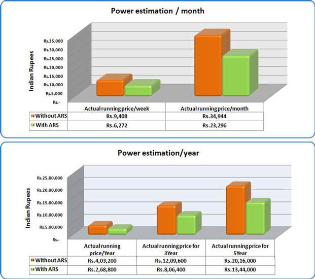
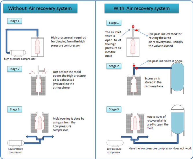
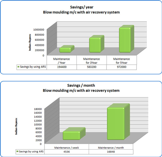
“ A PENNY SAVED IS PENNY EARNED” at UV TECH we are holistically concerned about the resource utilization of our customer. The Air Recovery System in the Fully Automatic Blow Moulding Machine is a stand out testimony our “We Care” attitude
In the package beverage the rejection pertaining to empty bottles often is the thin line that decides the magnitude of success of the project itself
There is often the misconception of subcontracting that forces the bottlers to procure blown bottles from small time vendors. This concept has fatal results when the rejection/damage of the bottles due to transportation hit hard on the bottom line of the project.
The other concept is to go in for semi automatic blowing machines, this seems to be a readymade solution for small timers whose filling line itself is not automated. This segment of the industry has very limited scope in terms of representing a bigger brand. Even in this case the handling rejection is often prohibitive.
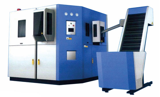
The fully automatic blow molding machine is considered a extravagant luxury in the bottling industry given the exorbitant cost of the machine, which is only supplemented by the ridiculously high operating cost and soaring electrical consumption. At UV Tech we have mastered the art of “having the cake and eating it too”. ie the a fully automatic blowing machine at an affordable cost complemented by low operating cost and reasonable electrical consumption
The U V Tech fully automatic blow molding machine is a “no touch by hand” state of the art equipment. It puts into unison a simple design and optimized productivity with minimum rejection.
The Preform is loaded on to a preform loader from where it is conveyed into the Preform unscrambler, this sets up the orientation of the Preform ”Neck Up” to be fed into the Oven. From the preform loader to the Oven the preform transfer is thro a turn table. Our sensitivity to quality begins even here, we have installed a sensor controlled Pneumatic Latch to ensure the preforms are not fed if the IR lamps have not reached the set temperature
In the oven the preform is heated thro 2 sections of IR lamps to the specified temperature. The temperature setting are dependent on the profile /resin. In Our Blow Molding Machine the Preform is heated Neck Up. Generally in the other fully automatic Blow molding machines the preform is heat neck down which means the requirement of an Servo Shuttling system becomes imperative. This has an huge impact on the Electrical consumption.
This process is necessary for the preforms to be heated homogeneously. This process again warrants the requirement of a chain and sprocket mechanism which again has an adverse impact on the power consumption of the equipment. U VTech has evolved a system which is akin to the roller mechanism known to man from time immemorial. In this system the preform is loaded in between two bearings when the preform touches a spring loaded soft metal pad it rotates. This mechanism does not have any major power requirement. Further the distance between the preforms inside the heater plays a major part in the energy saving of our machine. Normally in the conventional automatic blowing machine the inverted preform is loaded on to a mandrel mounted on a sprocket the minimum distance between the preform because of basic design limitation is 160mm approx. This air gap of 160mm is heated and consumes energy which could have otherwise been saved.
The heated preform is picked up by a pick and place tong mechanism. To be fed into the mould. We have not not gone by the conventional moulding which itself time consuming and requires highly skilled operators. In our machine the mould is mounted on a guides hence it is self aligning and very easy to load
The greatest advantage of this machine is “ A No Touch by Hand” line can be achieved. ie this blow molding machine can be directly integrated to Rinser filler Capper to achieve a fully automated line.
The machines are available in the following capacities
The rendering of a product irrespective of the power the brand determines the acceptance and eventually the success of the product.
Over the years the war of commodities has only increased multifold pushing the creativity and innovative marketing skills to the limit, wherein the limit itself seems to have the elastic modulus raised to the power of infinity.
With the demand ever on the rise and the manufacturers ever scrambling to usurp control over the ever growing market, the effort is no longer to dump the product in to a box and fling it into the market but to bring out the product and showcase it to the world at large.
To be succinct the endeavour is to “THINK OUT OF THE BOX” for the product, than to “BOX IT”.
The offering of packaged drinking water as a FMCG product has brought about an awareness that is no longer confined to the realm of the few quality control personal in a handful of manufacturers who are really cognizant to quality of their product. It is this awareness that has brought about To Know All attitude about the product. Given this scenario, the consumer wants to have a real closer look before the purchase is made.
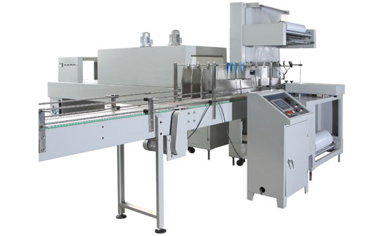
The carton box packing was the age old process that survived only for a lack of suitable alternative. The advent of shrink wrapping as an alternative has not only redefined the art of Product Offering but also has set a clear roadmap on the economics of packing.
The plight of the manufacturer is obvious when the despatches take place on a rainy day. The contention is not only to take care of the production woes but also to put in place all necessary precaution viz covering the truck with tarpaulin and plastic sheets to ensure the product successfully reaches the distributor. Even after this one leaky bottle would mean the entire column of cartons would never make it to the end user.
To add to this was the in process rejection, the labourers often trampled upon more cartons than they packed successfully, a scenario of “RUBBING SALT INTO THE WOUND”.
The answer to all this was the Shrink Wrap. It was a near perfect fairy tale endling to the packing woes of the the manufacturer. It not only was cost wise more effective but also reduced the transportation rejections drastically.
Given the opportunity to be a part of a solution, UVTECH jumped into the fray with our offering of The Shrink Wrapping Machine.
We at uvtech have analysed the requirements of the process and have put in place an equipment is capable of churning out 8-10 cases per min.
The equipment is PLC controlled and has a VFD that is infinitely responsive to the variations in output. The machine is completely powder quoted and atmost care has been taken in ensuring that the machine delivers a “No Touch By Hand Process”.
The economics and comparative analysis of Carton Packing vs Shrink wrapping is detailed for the reference of our esteemed users. Kindly note the comparative analysis does not take into account the costs due to rejection of cartons and the cost due to in process damage of cartons.
Jar Filling is a terminology that often sends the pulse racing in the packaged beverage industry.
The concept of pure treated water being available in jars started with an earnest attempts made by the early birds by supplies in a HDPE can of 25litres. The concept was prevalent till the mid 90s. The basic instinct of man to learn, unlearn & re-learn is often the cradle for the evolution of mankind. It is this basic instinct that found the HDPE wanting in terms of hygiene, safety and …………
The alternate was already in hand, “PET” & PC. The introduction of PET an PC brought about a change that was to stay. It also set the trend for standardization of the bulk packaged drinking water as a commodity. The product acceptability and demand saw major players jump into the fray in an effort to grab an undisputed niche market share. With the brands came the more sophisticated and automated packaging methodologies. The challenge was to deliver equipments that would stand up the 24 X 7 workload yet deliver in time the designed output, eliminate unwanted man power and turn out the most hygienic bulk packaged drinking water that was the “20 Ltr JAR” for the Indian market.
If there is a scenario of “Taking up a challenge and living up to it”, U V Tech by default will be there. With our automatic jar filling machine we not only opened up the doors for innumerous aspiring first generation entrepreneurs but also provided a plat form to for the brands to consolidate their ever growing market demand.
Over the years the U V Tech Jar filling machine has been the preferred choice of the Brands not only for their own facilities but also for their channel partners (FRANCHISEE).
The status a preferred O.E (original equipment) Supplier has been the result of being sensitive and proactive to needs of industry. An equipment is deemed successful not only by the automated features and its flawless appearance unless it is complimented by the user friendly operation and maintenance. These are the two prime requisites that often is the thin line that separates the preferred equipment from nightmarish equipment.
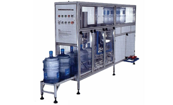
The U V Tech Jar filling machine is a combination of automated equipment with Aesthetic appearance and is also extremely user friendly.
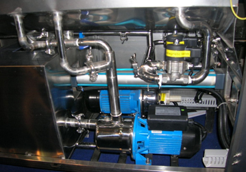
The basic equipment Material of Construction is Stainless Steel Grade 304 with all contact parts in Stainless Steel grade 316. The internal pipelines are with diary fittings ie triclover joints. The pumps are of Stainless Steel grade 304. The machine is equipped with a PLC (Programmed Logic Controller) that is nerve centre of the automation.
The Comparison Is Done On The Basis Of 100 Jars Being Washed In One Hour On A Normal Working Shift Of 8 Hours.
Manual washing 100 Jars/Hr | 20 ltrs Jar Machine 100 Jars/Hr |
---|---|
Manual washing requires more than 6- 8 workers for washing the Jars alone. | Requires only 1 person to load the Jar onto the machines Conveyor. |
Separate 2-3 workers are required for the Rinsing and Filling of the Jars. | This operation is completely automatic and Labour free. |
Manual handling (like dropping, throwing, sliding, etc) of Jars at each point leads to breakage and less life of the Jars. | There is absolutely no manual handling of any jar, as jars move from one stage to another purely on a Conveyor belt. Hence life of jar increases. |
Manual handling also leads to scratches and dents on the jar which reduces the look of the Jar. | No chance of scratches or any kind of dents possible during auto operation and hence enhances the life & looks |
Wastage of water is huge and nothing is actually recycled. | Water usage is minimal and all water is recycled at every single stage. |
Washing over a Time period is not exactly equal as during the start of the washing process. | As the system is automated the machine cleans all the jars equally on all counts. |
Cost of labour is huge and if workers do not report on time there is loss of production & Revenue. | Cost is reduced as the unit requires only 3 workers & any one can opt to do the production, due to easy operation. |
There are two models of Jar Filling Machine which are available in 4 different capacities namely.
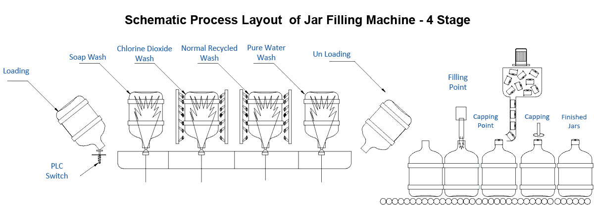
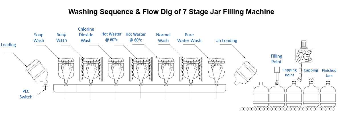
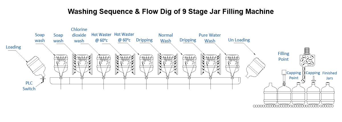
The main pre requisite for the 20 ltr jar is the thorough cleaning with is an absolute essentiality. To ensure this is achieved our machine is equipped with a seven stage wash as detailed below
In the rendering below we have out lined the various features that have made The U V Tech Jar filling machine a trusted Money spinner amongst Packers
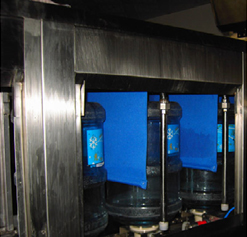
Stage separator curtains : to ensure that the cleaning medium from stage does not spill over to the adjacent stage
Double line feeding with internal cup holders mounted on chain conveyors
All pumps & pipelines used in the machine for washing, are in stainless steel 304. The filling line and the filling pump is in stainless steel 316. All joints in the pipeline are with tri-clover fittings with silicon o rings for easy maintenance and cleaning procedures.
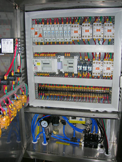
All pump contactors are of lg make , temperature controller and timers are of omron . Plc – panasonic make and an frl with pressure protector is provided inside the pannel itself
For a direct interaction our application engineers will be with you and explain in detail, and what more they would also facilitate a demo at the plant with one of our numerous customers
Jar Washing Machines Machinery Details. (for complete Tech Specs please see the Tech Specs table)
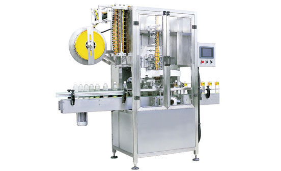
We are one of the leading manufacturers and suppliers of the Fully Automatic Shrink Label Machine. To assemble this machine, we use quality component that is manufactured following high definition engineering principles. Keeping in mind the defined industry standard, this is tested on various parameters in our inspection unit. Due to its durable finish standard, robust construction, high load bearing capacity, low maintenance and user friendly interface, our offered machine is highly demanded in various industries.